Bridge jigs (3D-printed)
Two 3D-printed fixtures for the slotted tie-bar bridge. The drill guide locates the string holes and carries the wing-shaping contours; the taper jig handles the top taper. The bridge blank (1″ wide × 7 mm thick × 104 mm long) arrives CNC pre-slotted for the saddle; these jigs handle everything after that. Used in Session 1.
Drill guide + wing template
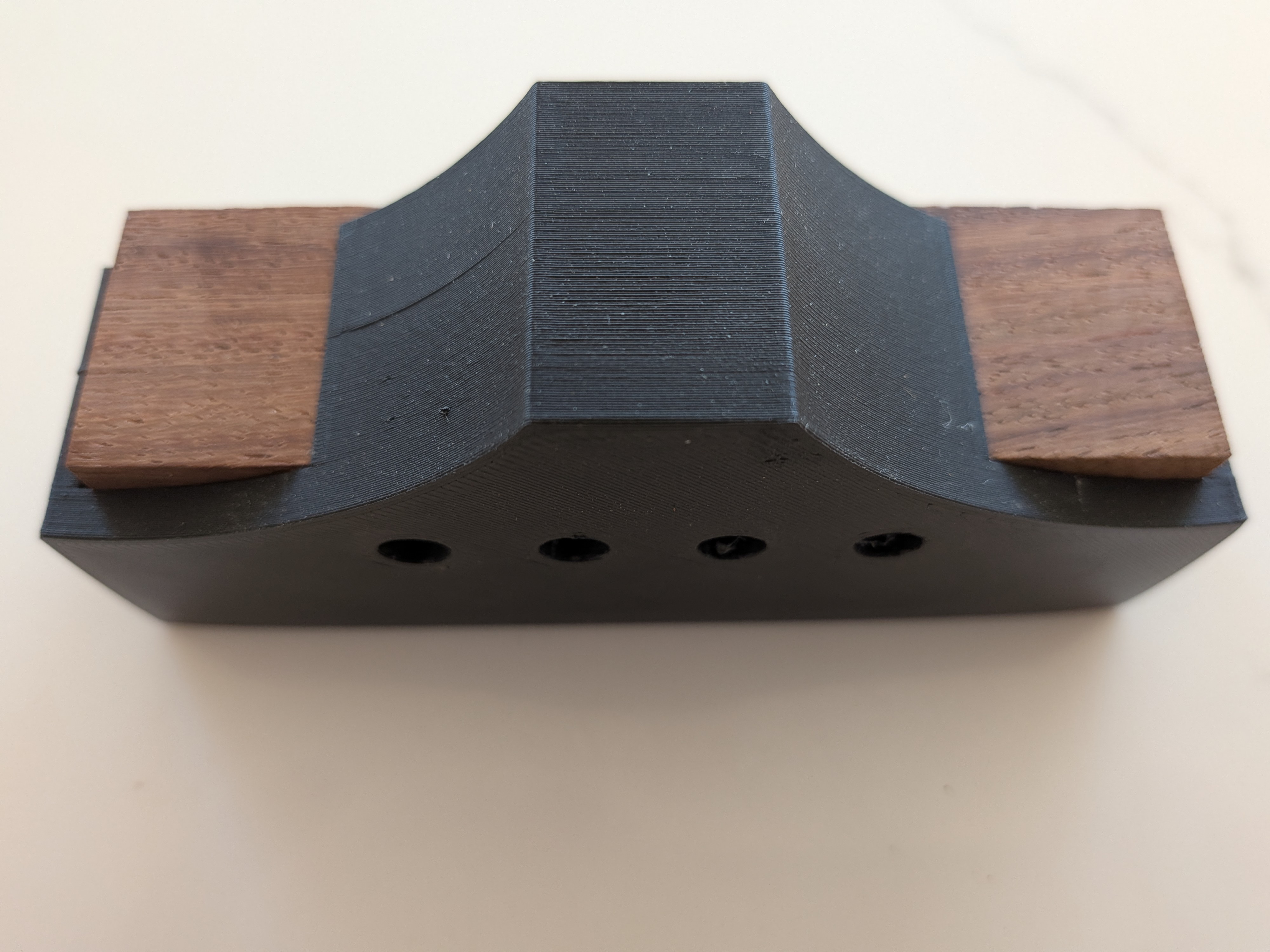
Blank seated in the jig, ready for drilling and wing shaping.
The drill guide does three jobs: its straight edges help size and square the stock, its four holes guide the string holes, and its curved shoulders establish the bridge-wing profile. Drop the blank in slot-up, with the tail side toward the jig's drill holes — get this backwards and the string holes land on the wrong side of the saddle slot. Drill the string holes 1/4″ (or the next size down), then shape the wings to the jig's curves (4″-diameter spindle on the spindle sander).
Taper jig (2° top slope)
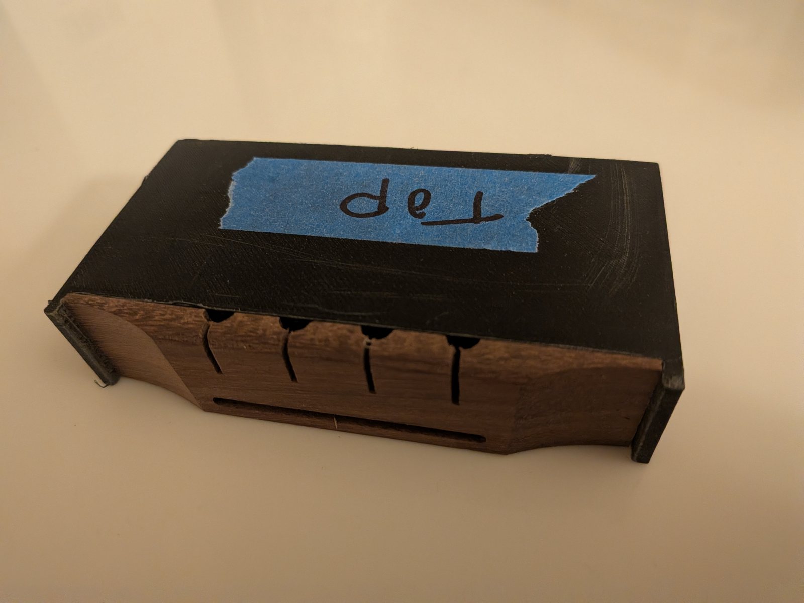
In the jig: the almost-finished bridge mounted for sanding, “Top” tape facing up.
The top of the bridge gets a subtle 2° slope — high at the saddle, falling toward the string-knot edge — so each string breaks cleanly over the saddle. This jig holds the almost-finished bridge (drilled, slotted, wings shaped) at exactly 2°: sand the exposed top square to the jig and the slope comes out right. Seat it fully with the “Top” tape facing up; it should sit flat with no rocking.
Print in PLA or PETG at 0.2 mm layers; no supports needed. The instructor demos both jigs in Session 1.